Wednesday, 1 November 2017

MPLS Basic - 1

Instead of forwarding packets based on the packets’ destination IP address, MPLS defines how routers can forward packets based on an MPLS label. By disassociating the forwarding decision from the destination IP address, MPLS allows forwarding decisions based on other factors, such as traffic engineering, QoS requirements, and the privacy requirements for multiple customers connected to the same MPLS network, while still considering the traditional information learned using routing
protocols.

With MPLS unicast IP forwarding, the MPLS forwarding logic forwards packets based on labels. However, when choosing the interfaces out which to forward the packets, MPLS considers only the routes in the unicast IP routing table.

Many of the more helpful MPLS applications, such as MPLS Virtual Private Networks (VPN) and MPLS traffic engineering (TE), use MPLS unicast IP forwarding as one part of the MPLS network.

CEF Review

The FIB entry details the information needed for forwarding: the next-hop router and the outgoing interface. Additionally, the CEF adjacency table lists the new data-link header that the router will then copy in front of the packet before forwarding. For the data plane, a CEF router compares the packet’s destination IP address to the CEF FIB, ignoring the IP routing table. CEF optimizes the organization of the FIB so that the router spends very little time to find the correct FIB entry, resulting in a smaller forwarding delay and a higher volume of packets per second through a router. For each packet, the router finds the matching FIB entry, then finds the adjacency table entry referenced by the matching FIB entry, and forwards the packet.

Overview of MPLS Unicast IP Forwarding

The term Label Switch Router (LSR) refers to any router that has awareness of MPLS labels, for example, Routers PE1, P1, and PE2. 
FIB: Used for incoming unlabeled packets. Cisco IOS matches the packet’s destination IP address to the best prefix in the FIB and forwards the packet based on that entry.
LFIB: Used for incoming labeled packets. Cisco IOS compares the label in the incoming packet to the LFIB’s list of labels and forwards the packet based on that LFIB entry.

The MPLS Header and Label

The MPLS header is a 4-byte header, located immediately before the IP header. The MPLS EXP bits allow for QoS marking, which can be done using CB Marking. The MPLS EXP bits allow for QoS marking, which can be done using CB Marking. The LSRs will decrement the MPLS TTL field, and not the IP TTL field, as the packet passes through the MPLS network.

MPLS TTL propagation refers to the MPLS routers propagate the same TTL value across the MPLS network—the same TTL values that would have occurred if MPLS was not used at all.

Cisco routers can be configured to disable MPLS TTL propagation. When disabled, the ingress ELSR sets the MPLS header’s TTL field to 255, and the egress E-LSR leaves the original IP header’s TTL field unchanged. As a result, the entire MPLS network appears to be a single router hop from a TTL perspective, and the routers inside the MPLS network are not seen from the customer’s traceroute command.

PE1 can be configured to use TTL propagation for locally created packets, which allows the traceroute command issued from PE1 to list all the routers in the MPLS cloud. At the same time, PE1 can be configured to disable TTL propagation for “forwarded” packets (packets received from customers), preventing the customer from learning router IP addresses inside the MPLS network. (The command is no mpls ip propagatettl.)

MPLS IP Forwarding: Control Plane

MPLS supports many different control plane protocols. For example, MPLS VPNs use two control plane protocols: LDP and multiprotocol BGP (MP-BGP). While multiple control plane protocols can be used for some MPLS applications, MPLS unicast IP forwarding uses an IGP and one MPLS-specific control plane protocol: LDP.

MPLS LDP Basics

For unicast IP routing, LDP simply advertises labels for each prefix listed in the IP routing table. To do so, LSRs use LDP to send messages to their neighbors, with the messages listing an IP prefix and corresponding label. By advertising an IP prefix and label, the LSR is essentially saying, “If you want to send packets to this IP prefix, send them to me with the MPLS label listed in the LDP update.”
The LDP advertisement is triggered by a new IP route appearing in the unicast IP routing table. Upon learning a new route, the LSR allocates a label called a local label. The local label is the label that, on this one LSR, is used to represent the IP prefix just added to the routing table

The routers in the MPLS cloud must use some IP routing protocol to learn IP routes to trigger the LDP process of advertising labels. Typically, for MPLS unicast IP routing, you would use an interior gateway protocol (IGP) to learn all the IP routes, triggering the process of advertising the corresponding labels. 

The MPLS Label Information Base Feeding the FIB and LFIB

LSRs store labels and related information inside a data structure called LIB. The FIB and LFIB contain labels only for the currently used best LSP segment, while the LIB contains all labels known to the LSR, whether the label is currently used for forwarding or not. To make a decision about the best label to use, LSRs rely on the routing protocol’s decision about the best route.

To enable MPLS for simple unicast IP forwarding, an LSR simply needs to enable CEF, globally enable MPLS, and enable MPLS on each desired interface. Also, IOS uses LDP by default. 

The term remote binding refers to a label-prefix binding learned through LDP from some LDP neighbor.

The FIB is used to forward packets that arrived unlabeled, and the LFIB is used to forward packets that arrived already labeled. 
show mpls forwarding-table 10.3.3.0 24
show mpls ldp bindings 10.3.3.0 24


Label Distribution Protocol Reference

LDP uses a Hello feature to discover LDP neighbors and to determine to what IP address the ensuing TCP connection should be made. LDP multicasts the Hellos to IP address 224.0.0.2, using UDP port number 646 for LDP.

After discovering neighbors through an LDP Hello message, LDP neighbors form a TCP connection to each neighbor, again using port 646.table. After the TCP connection is up, each router advertises all its bindings of local labels and prefixes


Monday, 25 September 2017

VRF Lite - 1

All router interfaces which provide transport for both types of traffic have been configured with two subinterfaces performing 802.1Q encapsulation; .10 for VLAN 10 (blue) and .20 for VLAN 20 (red).

VRF lite is simple: each routed interface (whether physical or virtual) belongs to exactly one VRF. Unless import/export maps have been applied, routes (and therefore packets) cannot move from one VRF to another, much like the way VLANs work at layer two. Packets entering VRF A can only follow routes in routing table A, as we'll see shortly.

Topology


After configuring, the routing tables are as follows:


--

----


----------------------------------

Trace route test from the Host PCs


Reachability from PC4 to PC1 is fine (BLUE vrf). The traceroute result shows PC4 <-> R3 <-> R2 <-> PC1.


Reachability from PC4 to PC2 is not working as they are in different VRF and 10.0.0.1 (FW) does not have a route to 192.168.x.x network.


Thursday, 31 August 2017

EEM Scripting

EEM Scripting - Interface Events

Embedded Event Manager is a feature of the Cisco IOS operating system that allows you to write handlers for various system events. The core of EEM is a special process known as an EEM server that acts as a middleware agent between event detectors and EEM event subscribers. There is a fixed number of event detectors that post an event when a programmed condition is met.
 CLI event detector – detects various commands typed in CLI based on regular expression matching
 Syslog event detector – responds to various syslog strings, allowing for matching on regular expressions just like CLI detector
 Interface counter – responds to various interface’s counters crossing threshold settings
 Counter – responds to the change of value of a generic system counter
 SNMP – monitors
 None –a special case of event detector triggered when a user issues the command "event manager run" to execute a named EEM script/applet
 Watchdog – generates periodic timer events and allows the EEM script to be run at repeating time intervals

The other parts of the EEM system—event subscribers—are defined and registered with the EEM server as either EEM applets or scripts. Applets are simple programs written using a very basic set of CLI commands that start with an action keyword. Scripts are special TCL scripts written to handle EEM events. The applets are easy to write and powerful enough to perform many functions including CLI commands, email sending, SNMP/Syslog message generation, and implementing basic program logic (such as branching or computations).

Every EEM applet has a name and a detector condition defined to trigger the applet. The applet may access global variables defined using the command event manager environment or the parameters passed to them by an event detector. There are predefined environment variables accessible to the EEM scripts, specific to every event detector.You may also list the variables for an event detector using the command show event manager detector <NAME> detailed. Every applet definition starts with a group of event commands that specify the event detector and the condition to trigger the applet. Normally there is only one event defined for an applet. If you define multiple events, you must further specify how they co-relate to each other

  event manager applet INTERFACE_LOAD
  event tag 1 interface name Serial0/0/0 parameter rxload entry-op gt entry-val 153 entry-type value poll-interval 30
  action 0.0 cli command "enable"
  action 1.0 cli command "conf t"
  action 2.0 cli command "interface Serial 0/0/0"
  action 3.0 cli command "ip access-group CRITICAL_TRAFFIC in"
  action 4.0 mail server "155.1.146.100" to "noc@INE.com" from "r5@INE.com" subject "Interface Alert" body "Interface ...

Register the applet with the “none” event detector to be able to run the applet from the CLI for “dry-run” testing purposes. Enable EEM debugging commands to track the CLI and E-Mail actions and run the applet manually first.
  event manager applet INTERFACE_LOAD
   event tag 2.0 none
  Rack1R5#debug event manager action cli
  Rack1R5#event manager run INTERFACE_LOAD


EEM Scripting - Syslog Events
---------------------------------------
  event manager applet INTERFACE_SHUTDOWN
  event tag 1.0 syslog pattern "Interface GigabitEthernet1.*changed.*down"
  action 1.0 cli command "enable"
  action 2.0 cli command "conf t"
  action 3.0 cli command "interface GigabitEthernet1"
  action 4.0 cli command "no shutdown"
  action 5.0 cli command "end"
  action 6.0 cli command "show users"


EEM Scripting: CLI Events
----------------------------------
The CLI event detector allows for monitoring certain CLI patterns and publishes an event if a match occurs. The event monitoring configuration could use the parameter sync set to either “yes” or “no” to define a synchronous or asynchronous applet. When the applet event condition is synchronous, the EEM server will hold the matched CLI command execution until the script terminates. The script should return an exit value in the variable $_exit_status , and this will determine whether the triggered command will run (status 1) or not (status 0). Asynchronous event handlers will let the CLI command execute and the event will be posted after that. The script cannot affect the command execution. Notice that asynchronous CLI events require a set of additional parameters, such as number of occurrences and the time window for the occurrences. Another command we use in the script below is the puts action. It allows you to display arbitrary text on the console, provided that the script is synchronous.

  event manager applet SHOW_RUN_FILTER
  event tag 1.0 cli pattern "show run" sync yes
  action 1.0 cli command "enable"
  action 2.0 cli command "show run | exclude username"
  action 3.0 puts $_cli_result
  !
  ! Exit status of 0 block execution of the original command
  !
  action 4.0 set $_exit_status 0
  R5#show event manager policy registered event-type cli

EEM Scripting: Periodic Scheduling
-----------------------------------------------
Event applets may be configured to respond to periodic or timed events—for example, to fire every time interval or start at a fixed time in the future.
  event manager applet SHOW_RUN_EVERY_5MIN
  event tag 1.0 timer watchdog time 300
  !
  ! We use write term as we intercepted show runin the previous task
  !
  action 1.0 cli command "enable"
  action 2.0 cli command "write term"
  action 3.0 syslog msg "Configuration Saved"


DHCP Relay
------------

DHCP relay is supposed to insert the “giaddr” field in the relayed DHCP packets, so that DHCP server may identify the pool to be used for the request. The choice of the pool is made based on the “giaddr” field or the incoming interface, if the “giaddr” is missing or zero . Option 82 serves as refinement to the request, allowing the DHCP server to select a “sub-range” in the pool. (Notice that by default Cisco IOS devices reject packets with zero “giaddr” and by default Cisco Catalyst switches use “giaddr” of zero when configured for DHCP snooping!) A switch with DHCP Snooping enabled will drop packets on untrusted ports that contain Option 82 or have a non-zero giaddr (e.g. 0.0.0.0).
just a couple of sub-options, namely the “remote-id” (option ID 0×2) and the “circuit-id” (ID 0×01). Those two are supposed to identify the remote device and the port where the DHCP request was received.

the giaddr is used in DHCP relay scenarios to indicate which pool/subnet the DHCP server should assign the address from.
Option 82 is used in provider networks to give extra information to the DHCP server regarding where a device is located.
we have two options:
 1. Tell the switch not to set Option 82
no ip dhcp snooping information option
 2. Tell the router to ignore Option 82
ip dhcp relay information trust-all  --This command instructs the DHCP server that blank giaddr is acceptable, even if option 82 is set.

Tuesday, 30 May 2017

Quality of Service - 2

MQC Class-Based Generic Traffic Shaping

The purpose of traffic shaping is to “format” an outbound packet flow so that it conforms to a traffic contract. The formatting process slows down the average bitrate and the packet flow structure, resulting in a traffic flow consisting of uniformly spaced traffic bursts. For example a customer buys an Ethernet circuit provisioned at 10Mbps, but the physical link to the provider is FastEthernet (100Mbps). Since the customer’s interface always serializes packets outbound at 100Mbps, and the service provider performs traffic policing/admission control inbound, shaping is needed on the customer side.

To slow the rate down, the first task of the shaper is to meter the traffic coming into the output queue, and decide whether it exceeds the target average rate. The concept of metering is based on the fact that traffic leaves an interface in a serial manner (bit by bit, packet by packet), and that packets are usually grouped in bursts, separated by periods of interface silence. While the router sends each burst at AR speed, the spacing between bursts makes the average rate less than the AR. The goal of metering is to mark those bursts that exceed (do not conform to) the desired average rate, called the Committed Information Rate (CIR).

The metering function of traffic shaping uses what is known as a token bucket model to determine if traffic conforms to, or exceeds, the average rate. Every time a packet tries to be de-queued to the transmit ring, the metering function compares the size of the packet trying to leave to the amount of tokens, or credit, in the token bucket. If the size of the packet is less than or equal to the amount of credit, the packet conforms and is sent. If the size of packet is greater than the amount of credit in the token bucket, the packet exceeds, and is delayed. The size of the token bucket is calculated by taking the desired average rate (CIR) in bits per second, and breaking it down into a smaller value of bursts in bits per interval in milliseconds. These values are expressed as Bc (Burst Committed) bits, and Tc (Time Committed) milliseconds. The size of the token bucket is Bc bits. Essentially every Tc period, the token bucket is refilled with the Bc amount in bits. Think of the Bc bits as tokens going into the bucket every Tc interval. The key point here isthat Bc bits per Tc interval is the same value as CIR bits per second, but is simply expressed in smaller units.

If packet exceeds because there are not enough tokens in the bucket, the shaping process delays the packet and holds it in the internal shaping queue. By this logic, even though traffic is always sent at the AR, the periods of delay incurred by non-conforming traffic in the shaping queue results in the overall average rate (CIR) being lower than the AR. The size of Tc is not manually configurable, however it is configured indirectly by configuring the CIR and the Bc values based on the formula Bc = CIR * Tc/1000; Tc is in milliseconds.

One possible problem with the above calculation for Bc is the case that the packet trying to be de-queued is larger than Bc, which means that there would never be enough credits in the token bucket to send it. For example if a packet’s size is 1500 bytes, but the Bc is only 1000 bytes. To deal with this situation the shaper calculates a deficit counter (e.g. 1000-1500=-500) and adds this counter to the accumulated credit in the next round (next Tc interval). In effect this reduces the amount of traffic to send the next time around.  To avoid this problem altogether ensure that Bc is greater than the average packet size, which will achieve a smoother packet distribution. This is not always possible though, since there are cases when CIR value is too low. In the latter case, layer 2 fragmentation can be introduced. The next problem case that the scheduler can run into is when it has no traffic to send during a time interval (e.g. a pause in the packet stream), but it has more than Bc bits to send in the following time interval. Based on the leaky token bucket algorithm, no more than Bc bytes can be sent per Tc interval, even if in previous intervals it did not send enough traffic. The result of this is that the shaper achieves less than the desired average rate. To resolve this problem, traffic shaping uses what is known as a dual leaky token bucket, with the first token bucket represented as Committed Burst (Bc) and the second token bucket as Excess Burst (Be).

The Excess Burst bucket is only filled in the case that the full Bc bucket was not emptied in the previous interval. The extra credits, or tokens, left over from the Bc bucket are then moved to the Be bucket before the Bc bucket is refilled. For example, if the Bc size is 10 bits, but only 8 bits were sent in the current interval, a credit of 2 bits can be moved to the Be bucket if space is available. During the next interval, the scheduler can now de-queue up to Bc+Be bits. If Bc capacity is again not used completely, the left over credits are moved to Be, up to its maximum size.

Like Bc, Be has a finite size defined which controls how much credit can be stored. The size of the Be bucket is constrained by the Access Rate of the physical link, since the packets are always serialized at this rate. Therefore the maximum Be value (maxBe) is equal to (AR-CIR)*Tc/1000 which implies that if the shaper sends Bc+maxBe per Tc, it is sending at the Access Rate. The Be value can be set lower than maxBe, but should never exceed maxBe. Note that since Be is only populated due to a lack of Bc being used, the average sending rate over time still never exceeds the CIR.

With the command shape average under the policy-map class configuration, the CIR, Bc, and Be are defined. We used class-based shaping to limit the sub-interfaces sending rate. This is a common use of GTS(Generic Traffic Shaping), and the effect is that each sub-interface now uses its own software queue, whereas by default, all sub-interfaces share the software queue of their main interface. This also allows the use of separate QoS policies per sub-interface, because of the ability to tune shaper’s queue.

Using Ethanalyzer on Nexus platform for control-plane and data-plane traffic analysis

Ethanalyzer does not capture data traffic that Cisco NX-OS forwards in the hardware but you can use ACLs with log option as a workaround using ACL logging to sample specific packets from data plane.

When we use ACLs and the “log” keyword, access control entries (ACEs) with log keyword cause system to punt a copy of matching packets to supervisor CPU. Key point is that original traffic forwarded or dropped in hardware with no performance penalty. Note that punted copies subjected to hardware rate limiter, forwarding engine hardware enforces rate to avoid saturating inband interface/CPU.

hardware rate-limit access-list-log command adjusts rate (100 pps by default).

Full Packet Analysis

1. Define ACL entry with logging to match traffic of interest
ip access-list acl-cap
permit tcp 10.1.1.3/32 10.1.2.2/32 eq 5000 log
permit ip any any

2. Attach ACL to interface
interface e1/1
ip access-group acl-cap in

3. Define ethanalyzer capture and/or display filter to capture just the subject traffic
ethanalyzer local interface inband capture-filter “tcp port 5000”

4. View captured traffic on-switch, or copy to PC/workstation for GUI analysis
Example – Brief Decode On-Switch
n7010# ethanalyzer local interface inband brief capture-filter "tcp port 5000" limit-cap 3

Example – Full Decode On-Switch
n7010# ethanalyzer local interface inband capture-filter "tcp port 5000" limit-captured-frames 1 | no-more

Example – Write Data to File
n7010# ethanalyzer local interface inband capture-filter "tcp port 5000" limit-captured-frames 50 write bootflash:test.cap

Example Captures
This example shows detailed captured data for one HSRP packet:
switch(config)# ethanalyzer local interface mgmt capture-filter "udp port 1985"
limit-captured-frames 1

Other filter examples:

ethanalyzer local interface mgmt capture-filter “dst host 172.16.185.1”
ethanalyzer local interface inband capture-filter “stp”
ethanalyzer local interface inband decode-internal capture-filter “stp”
ethanalyzer local interface inband capture-filter “stp” limit-frame-size 64
ethanalyzer local interface inband capture-filter “icmp and host 10.10.10.1” limit-captured-frames 1000 write bootflash:icmp

Wednesday, 24 May 2017

Quality of Service - 1

MQC Bandwidth Reservations and CBWFQ

Ethernet Sub-Interfaces do not have a way to get the state of congestion that their underlying physical, or "main," interface may be experiencing. Due to this reason, a queuing policy applied directly to a subinterface would have no way to know when the link is congested, and thus would
never trigger. As such, Cisco IOS does not allow direct application of a policy-map that uses any sort of queuing policies directly to sub-interfaces. A way to overcome this limitation is to apply a policy that shapes the rate of the subinterface to create artificial congestion. This type of configuration is referred to as HQF, or Hierarchical Queuing Framework.

The logic of CBWFQ is that during congestion, a class with a bandwidth reservation of ClassBandwidth will have at least a ClassBandwidth/ InterfaceBandwidth share of the total interface bandwidth. CBWFQ reservation only becomes active when congestion occurs.

The CLI will not allow you to assign a service-policy with CBWFQ weights unless the interface is using FIFO queuing, which implies that CBWFQ is not compatible with any of the legacy queuing methods, such as custom queueing or priority queueing. These must be disabled explicitly before applying the service policy.

Each class configured with a bandwidth statement under the policy-map has its own dedicated FIFO queue in the interface’s CBWFQ conversation pool. The depth of each FIFO queue can be changed on a per-class basis with the queue-limit command. The overall WFQ settings, such as the CDT and the total queue size, can be set using the queue-limit under class-default, and the hold-queue <number> out command at the interface level.

As soon as the bandwidth keyword is specified under any user-defined class, the interface queue turns into CBWFQ. This means that any unmatched flows that fall back into class-default are scheduled using dynamic WFQ weights. This means that automatic classification occurs, along with precedence-based weight assignment and sharing of the single buffer space of WFQ. This behavior is default, even if you did not configure fair-queue under the class-default. If you want to disable fair-queue for unclassified packets, an explicit bandwidth value for the class-default can be configured, which turns it into a single FIFO queue.

Moreover, if you do not define any classes other than class-default, and class default has a bandwidth value defined, the entire interface queue essentially becomes a FIFO queue.
policy-map TEST
class class-default
bandwidth 96


Bandwidth Reservations and CBWFQ

It is not possible to mix the bandwidth and bandwidth percent commands in the same policy map; the units must be the same among classes.


MQC LLQ and Remaining Bandwidth Reservations

To prevent starvation of other queues, the packets de-queued from the LLQ conversation are metered using a simple token bucket, with a configurable rate and burst size. Packets that exceed the token bucket are dropped (policed) during times of congestion; if there is no congestion, exceeding traffic is not dropped, but it is simply not prioritized. Multiple classes inside a single policy-map can use the priority keyword, but only a single priority queue exists. This design of multiple priority classes is used to ensure that one priority flow does not starve another priority flow.

When the LLQ priority reservation is configured, the CBWFQ algorithm subtracts the reserved bandwidth of the priority queue from the interface’s available bandwidth or from the available rate based on the shaping policy. The remaining bandwidth can be used to create a relative bandwidth reservation for other classes in the CBWFQ.
bandwidth remaining percent

MQC WRED

CBWFQ supports three drop policies: classic tail-drop, which is the default for user-defined classes, Congestive Discard for WFQ, and Random Early Detection (RED).
When you apply the random-detect command under a user-defined class, it automatically removes the MQC LLQ and Remaining Bandwidth Reservations (pending update) command and enforces RED as the drop policy. When using RED with CBWFQ, each flow is considered an individual FIFO queue. This is similar to legacy flow-based WRED; the big improvement is the ability to use random drop per flow, not per whole queue. 


MQC Dynamic Flows and WRED

There are two ways to enable WRED within class-default. The first is to configure a bandwidth reservation statement (turning the class’s queue into a FIFO queue) and then enabling RED, and the second is to enable RED with WFQ. The second case
activates RED dropping to replace Congestive Discard Threshold-based drops for dynamic flows. 

MQC WRED with ECN

TCP Explicit Congestion Notification (ECN), similar to BECN and FECN in Frame Relay, is used to signal the forthcoming of network congestion for TCP flows. Originally, TCP detected network congestion based on packet loss, timeouts, and duplicate acknowledgments. This was usually the result of full queues and unconditional packet drops. TCP ECN allows the network to signal the receiver of the flow that the network is close to dropping packets. It’s then up to the TCP receiver to decide how to react to this notification; it usually signals the sender to slow the sending rate. The overall effect of TCP ECN is better performance, compared to simple packet drops and slow start, because it allows the sender to respond faster than slow start would and results in less time spent on the recovery from a packet loss.
TCP ECN works together with RED by changing the exceed action from random drop to ECN marking. Instead of randomly dropping a packet when the average queue depth grows above the minimum threshold, RED marks packet with the special ECN flag. 
!
ip tcp ecn
!
policy-map AAA
class BBB
random-detect
random-detect ecn

Wednesday, 15 February 2017

BGP - 2 - BGP Routing Policies

Route Filtering and Route Summarization

Four popular tools used to filter BGP routes:

  1. Distribution lists
  2. Prefix lists
  3. AS_PATH filter lists
  4. Route maps

Additionally, the aggregate-address.

The four main tools have the following features in common:

  • All can filter incoming and outgoing Updates, per neighbor or per peer group.
  • Peer group configurations require Cisco IOS Software to process the routing policy against the Update only once, rather than once per neighbor.
  • The filters cannot be applied to a single neighbor that is configured as part of a peer group.
  • Each tool’s matching logic examines the contents of the BGP Update message, which includes the BGP PAs and network layer reachability information (NLRI).
  • If a filter’s configuration is changed, a clear command is required for the changed filter to take effect.
  • The clear command can use the soft reconfiguration option.


Filtering BGP Updates Based on NLRI

One difference between BGP distribute lists and IGP distribute lists is that a BGP distribute list can use an extended ACL to match against both the prefix and the prefix length. When used with IGP filtering tools, ACLs called from distribute lists cannot match against the prefix length.
The prefix list matches the exact prefixes and prefix lengths; the omission of any ge or le parameter means each line matches only that exact prefix.

Both the route map and any referenced ACL or prefix list have deny and permit actions configured. The route-map command’s action—either deny or permit —defines whether an NLRI is filtered ( deny ) or allowed to pass ( permit ). The permit or deny action in an ACL or prefix list implies
whether an NLRI matches the route map clause ( permit by the ACL/prefix list) or does not match ( deny in the ACL/prefix list).

To support soft reconfiguration, BGP must remember the actual sent and received BGP Update information for each neighbor. The neighbor neighbor-id soft-reconfiguration inbound command causes the router to keep a copy of the received Updates from the specified neighbor. (IOS keeps a copy of sent Updates automatically.) 
For configuration changes that impact the local injection of routes into the BGP table, soft reconfiguration does not help. The reason is that soft
reconfiguration simply reprocesses Updates, and features that inject routes into BGP through the redistribute or network commands are not injected based on Update messages.

Comparing BGP Prefix Lists, Distribute Lists, and Route Maps

If the desired policy is only to filter routes based on matching prefixes/lengths, a route map does not provide any additional function over using a distribute list or prefix list directly. Similarly, if the goal of the policy is to filter routes just based on matching with an AS_PATH filter, the route map does not provide any additional function as compared to calling an AS_PATH filter directly using the neighbor filter-list command. However, only route maps can provide the following two functions for BGP routing policy configurations:
  • Matching logic that combines multiples of the following: prefix/length, AS_PATH, or other BGP PAs.
  • The setting of BGP PAs for the purpose of manipulating BGP’s choice of which route to use

Filtering Subnets of a Summary Using the aggregate-address Command

The filtering options on the aggregate-address command are as follows:
  • Filtering all component subnets of the summary from being advertised, by using the summary-only keyword
  • Advertising all the component subnets of the summary, by omitting the summaryonly keyword
  • Advertising some and filtering other component subnets of the summary, by omitting the summary-only keyword and referring to a route map using the suppressmap keyword.

Filtering BGP Updates by Matching the AS_PATH PA

To filter routes by matching the AS_PATH PA, Cisco IOS uses AS_PATH filters.
The main two steps are as follows:
  1. Configure the AS_PATH filter using the ip as-path access-list number { permit | deny } regex command.
  2. Enable the AS_PATH filter using the neighbor neighbor-id filter-list as-path-filter-number { in | out } command.
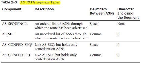
Because the most recently added ASN is the first ASN in the AS_SEQUENCE segment, the process of adding the ASN before advertising routes to external BGP (eBGP) peers is called AS_PATH prepending. 


Including the as-set keyword, R4 creates an AS_SET segment in the AS_PATH of the aggregate route. Note that the AS_SET segment is shown in brackets, and it is listed in no particular order. These facts are all important to the process of AS_PATH filtering.


Confederation ASNs are used to prevent loops inside the confederation. Because these ASNs will be removed before advertising the route outside the full AS, the confederation ASNs are kept inside a different segment—the AS_CONFED_SEQ segment. Finally, if a route is aggregated inside a confederation, the AS_CONFED_SET segment holds the confederation ASNs with the same logic as used by the AS_SET segment type, but keeps them separate for easy removal before advertising the routes outside the confederation.


The show ip as-path-access-list command shows the contents of the list.
The show ip bgp neighbor neighbor-id advertised-routes command displays the routes actually sent—in other words, this command reflects the effects of the filtering by omitting the filtered routes from the output.
The show ip bgp neighbor neighbor-id received-routes command displays the routes actually received from a neighbor, never omitting routes from the output, even if the router locally filters the routes on input.
Output filter lists are applied before the router adds its own ASN to the AS_PATH.

A couple of ways to test regex without changing the routing policy.
show ip bgp neighbor 10.1.34.4 received-routes | include 4_1_.*_.*_.*_44
This command parses the entire command output using the regex after the include keyword.
The other method to test a regex is to use the show ip bgp regexp expression command. This command parses the AS_PATH variables in a router’s BGP table, including all special characters. However, the regexp option of the show ip bgp command is not allowed with the received-routes or advertised- routes option.

Note that the "(" must be matched by enclosing it in square brackets, as ! the "(" itself and the ")" are metacharacters, and would otherwise be interpreted as a metacharacter. Without the "[(]" to begin the regex, the ! AS_PATH filter would not match. Because the "{" and "}" are not metacharacters, they can simply be typed directly into the regex.

BGP Path Attributes and the BGP Decision Process

Each BGP PA can be described as either a well-known or optional PA. 
Well-known PAs are either one of the following:
  • Mandatory: The PA must be in every BGP Update.
  •  Discretionary: The PA is not required in every BGP Update.


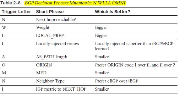
The BGP Decision Process

  1. Is the NEXT_HOP reachable?
  2. Highest administrative weight
  3. Highest LOCAL_PREF PA
  4. Locally injected routes
  5. Shortest AS_PATH length: The length calculation ignores both AS_CONFED_SET and AS_CONFED_SEQ, and treats an AS_SET as one ASN, regardless of the number of ASNs in the AS_SET. It counts each ASN in the AS_SEQUENCE as one. (This step is ignored if the bgp bestpath as-path ignore command is configured.)
  6. ORIGIN PA
  7. Smallest Multi-Exit Discriminator (MED) PA: The smaller the value, the better the route.
  8. Neighbor Type: Prefer external BGP (eBGP) routes over internal BGP (iBGP).
  9. IGP metric for reaching the NEXT_HOP.
If a step determines the best route for an NLRI, BGP does not bother with the remaining steps.
When overlapping NLRIs exist—for example, 130.1.0.0/16, 130.2.0.0/16, and 130.0.0.0/12—BGP attempts to find the best route for each specific prefix/prefix length.
First and last of the nine items relate to NEXT_HOP.


Configuring BGP Policies

The show ip bgp <network> command lists the advertising router’s RID and neighbor ID.
The "from z.z.z.z" phrases identify the neighbor ID that advertised the route. The "(y.y.y.y)" output that follows lists the RID of that same router.


Step 1: NEXT_HOP Reachable
Step 2: Administrative Weight
Default 0 for learned routes, 32,768 for locally injected routes
The neighbor route-map command creates an implied filtering decision. Any route matched by a permit clause in the route map is implied to be allowed through, and routes matched by a deny clause will be filtered. Route maps use an implied deny all at the end of the route map for any unmatched routes. By including a final clause with just a permit keyword, the route map changes to use permit all logic, thereby passing all routes.

Step 3: Highest Local Preference (LOCAL_PREF)
Changing the default Using the bgp default local-preference <0-4294967295> BGP subcommand

Step 4: Choose Between Locally Injected Routes Based on ORIGIN PA
When the same NLRI is locally injected into BGP from multiple methods, pick the route with the better ORIGIN PA.

Step 5: Shortest AS_PATH
bgp bestpath as-path ignore command - Removes the AS_PATH length step from the decision tree for the local router.
Removing Private ASNs - 
 Private ASNs can be removed only at the point of sending an eBGP Update.
 If the current AS_SEQ contains both private and public ASNs, the private ASNs will not be removed.
 If the ASN of the eBGP peer is in the current AS_PATH, the private ASNs will not be removed, either.

The aggregate-address command with the as-set option can lengthen the AS_PATH length calculation as well.
The BGP AS_PATH length calculation counts the entire AS_SET as 1, regardless of the actual length.

Step 6: Best ORIGIN PA
The well-known mandatory BGP ORIGIN PA characterizes a route based on how it was injected into BGP. 
If the set of routes to reach a single NLRI includes only one route of ORIGIN code IGP (i), and all the others as incomplete (?), the route with ORIGIN i is the best route. BGP routing policies can set the ORIGIN code explicitly by using the set origin route
map subcommand, although the earlier steps in the BGP decision process are typically better choices.

Step 7: Smallest Multi-Exit Discriminator
Scope - Advertised by one AS into another, propagated inside the AS but not sent to any other ASs. Smaller is better.
The purpose of the MED (or MULTI_EXIT_DISC) is to allow routers in one AS to tell routers in a neighboring AS how good a particular route is. A default setting is 0. MED. A better default for MED can be set by using the bgp bestpath med missing-as-worst BGP subcommand, which resets a router’s default MED to the largest possible MED value, instead of the lowest.

Configuring MED: Multiple Adjacent Autonomous Systems
By default, a Cisco router ignores MED when the multiple routes to a single NLRI list different neighboring ASNs. This default action makes sense—normally you would not expect two different neighboring ISPs to have chosen to work together to set MEDs. To override this default and consider the MED in all cases, a router needs to configure the bgp always-compare-med BGP subcommand. If used on one router, all routers inside the
same AS should also use the bgp always-compare-med command, or routing loops can result.
After reaching the other AS, the MED is advertised inside the AS, but not outside the AS.
MED can also be set through inbound route maps, although that is not the intended design with which to use MED.

Step 8: Prefer Neighbor Type eBGP over iBGP
BGP uses this decision point frequently when two or more enterprise routers connect to the same ISP.
Each enterprise border router knows of one eBGP route to reach each prefix, and one or more iBGP routes to the same prefix learned from that enterprise’s other border routers. With no routing policies configured, the routes tie on all decision points up to this one, including AS_PATH length, because all the prefixes were learned from the same neighboring ISP. The decision process reaches this step, at which point the one eBGP route is picked as the best route.

Step 9: Smallest IGP Metric to the NEXT_HOP
Step 10: Lowest BGP Router ID of Advertising Router
Step 11: Lowest Neighbor ID

The BGP maximum-paths Command

BGP defaults the maximum-paths command to a setting of 1. However, BGP will consider adding multiple entries to the IP routing table, for the same NLRI, under certain conditions—conditions that differ based on whether the best route is an eBGP route or an iBGP route.

The following rules determine if and when a router will add multiple eBGP routes to the IP routing table for a single NLRI:
  1. BGP must have had to use a tiebreaker (Step 10 or 11) to determine the best route.
  2. The maximum-paths number command must be configured to something larger than the default of 1.
  3. Only eBGP routes whose adjacent ASNs are the same ASN as the best route are considered as candidates.
  4. If more candidates exist than that called for with the maximum-paths command, the tiebreakers of Steps 10 and 11 determine the ones to use.
The rules for iBGP have some similarities with eBGP, and a few differences, as follows:
  1. Same rule as eBGP rule 1.
  2. The maximum-paths ibgp number command defines the number of possible IP routes, instead of the maximum-paths number command used for eBGP.
  3. Only iBGP routes with differing NEXT_HOP settings are considered as candidates.
  4. Same rule as eBGP rule 4.

BGP Communities

The BGP COMMUNITY PA provides a mechanism by which to group routes so that routing policies can be applied to all the routes with the same community. 
BGP communities are powerful in that they allow routers in one AS to communicate policy information to routers that are one or more autonomous systems distant. In fact, because the COMMUNITY PA is an optional transitive PA, it can pass through autonomous systems that do not even understand the COMMUNITY PA and then still be useful at another downstream AS.
The only way to match the COMMUNITY is to refer to an ip community-list , which then has the matching parameters.

The set community 10 20 30 additive command would add the values to the existing COMMUNITY string.


The show ip bgp community-list list-number command is then used to show whether a match would be made. This command lists the entries of the BGP table that match the associated COMMUNITY PA, much like the show ip bgp regex command examines the AS_PATH PA.

The set community none command in a route-map clause, and all routes matched by that clause will have their COMMUNITY PA removed. A route map can also remove individual COMMUNITY strings by using the set commlist community-list-number delete command.

Filtering NLRIs Using Special COMMUNITY Values

A route with COMMUNITY NO_EXPORT is not advertised outside an AS. This value can be used to prevent an AS from being a transit AS for a set of prefixes. 
Finally, routes with these settings can be seen with commands like show ip bgp community noexport, with similar options NO_ADVERT and LOCAL_AS.

Fast Convergence Enhancements
BGP only provides updates to its neighbors periodically using an interval based on the peering type: iBGP peers receive updates every 5 seconds, whereas eBGP peers are updated only every 30 seconds. BGP will only verify next-hop reachability every 60 seconds.

Fast External Neighbor Loss Detection
The eBGP session between directly connected eBGP neighbors will be torn down the moment that the connected subnet between the peers is lost. This will result in the immediate flushing of BGP routes, and BGP will immediately begin looking at alternate routes. 

Internal Neighbor Loss Detection
With the neighbor fall-over command, the moment that the IP address of the BGP peer is removed from the routing table, the BGP session with the peer will be torn down, thus resulting in immediate convergence. 

EBGP Fast Session Deactivation
Use it to quickly detect failures of eBGP sessions established between loopback interfaces of eBGP peers or to detect eBGP neighbor loss when you disable fast external fall-over.

Summary

network ip-address backdoor 
- BGP mode; identifies a network as a backdoor route, considering it to have the same administrative distance as iBGP routes