Friday 2 September 2016

OSPF - Labbing Notes 2

OSPF is sometimes described as being partially link-state and partially distance vector. This is because SPF calculations are only performed for Intra-Area routing, whereas the Area Border Routers’ (ABRs) advertised information is trusted for Inter-Area and External calculations. R10 does not know the detailed information about the path selection that is occurring behind R5 (ABR). R10 trusts R5’s calculation for the prefix, which is typically a distance vector behavior, and then calculates the shortest Intra-Area path to reach R5, which is a link-state behavior.

Metric of the route is 41 and it’s an ospf inter-area route. Next hop is 155.1.108.8 and the route is from 150.1.5.5 with the cost of 21.


First finding out who R10 is adjacent with by viewing its Router LSA (LSA 1).


So, from above total cost from R10 to 150.1.6.6 is 21+10+10=41. 
Now, let’s see how R5 gets the cost of 21.


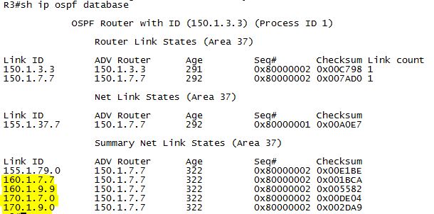
To view possible paths to Network Summary LSA (LSA 3), below shows both R1 and R4 with advertising cost of 11.


To find shortest path cost to R1 and R4, 


The cost to reach all ABR routers can also be identified from the following output.


Setting a ospf cost for an interface is only effective for its router’s shortest path calculation; not the directly connected router at the other end of the interface. OSPF cost calculation for a segment is based on the bandwidth value of the outgoing interface.
To have different OSPF cost per neighbor, the network type’s point-to-multipoint and point-to-multipoint non-broadcast support the setting of the OSPF cost value on a per-neighbor basis.
---------------------------------------------------------------------------------------

Inter-area routing can only occur through area 0.
Non-backbone (not area 0) areas can be used for inter-area transit if a shorter path can be found through them, and if the "TransitCapability parameter has been set to TRUE in Step 2 of the Dijkstra algorithm." In Cisco’s IOS implementation, this flag is controlled with the capability transit routing process-level command, and is on by default. The design case when the feature is used is very specific and has to do with a shorter Inter-Area path being found via a non-area 0 router as compared to the target router of a virtual-link.

Flooding Reduction – LSA’s LS age is never incremented past the value MaxAge. When the link state age reaches MaxAge, the router must attempt to flush the LSA by reflooding the MaxAge LSA just as if it was a newly originated LSA. MaxAge value is 3600 sec or 60 minutes by default. To ensure the an LSA is not aged out, which means it will be flushed from the OSPF database, each LSA is reflooded after 30 minutes, regardless of whether the topology is stable or not. This periodic flooding behavior is commonly referred to as the “paranoid update.” The ip ospf flood-reduction feature stops unnecessary LSA flooding by setting the DoNotAge (DNA) bit in the LSA, removing the requirement for the periodic refresh. This needs to be enabled on links with OSPF neighbors attached.

OSPF Summarization
Because devices in an OSPF area require the same copy of the database to compute correct SPF, filtering or summarization of routes in the database can only occur between areas or domains, not within an area. Use "area <area no from where routes summarized> range address mask".
External OSPF summarization is configured at the redistribution point between routing domains with the summary-address command.

The Forward Address: 0.0.0.0 field means that R5 must now compute the metric toward the advertising router, ASBR, and install this metric in the routing table as the forward metric.


The calculation for External Type-1 OSPF routes does not distinguish in the routing table between the metric reported by the ASBR and the metric to the ASBR via the forward metric. Instead, External Type-1 routes represent the metric as one cumulative value of the reported metric and the metric to the ASBR.


OSPF Stub Area
The stub area, is used to remove Type-5 External link states from the database and replace them with a default route. When an OSPF router redistributes a route into the domain, it originates a Type-5 External LSA representing the route and its attributes. Inside this LSA, the originating router sets the advertising router field to its local router-id and, generally, the forward address field to 0.0.0.0. When an OSPF router in the same area as the originator looks up the Type-5 LSA, it looks at the forward address. If the forward address is set to 0.0.0.0, it means that the traffic should be sent toward the advertising router to reach the destination. To find out how to reach the advertising router, the advertising router’s Type-1 Router LSA is consulted, and intra-area SPF is performed. This is similar to inter-area routing logic, because the router doing the lookup does not compute SPF to the final destination, only the intermediary advertising router.
For external routing between areas, the logic is modified slightly. When an Area Border Router receives a Type-5 External LSA from a device in its own area and passes it into a different area, a Type-4 ASBR Summary LSA is generated. The Type-4 LSA tells devices in the new area how to forward toward the ASBR, which in turn tells them how to forward toward the external route.

OSPF NSSA
When the Type-7 NSSA External LSA is received by the ABR and is moved into area 0, the information contained in the Type-7 LSA is translated to a normal Type-5 External LSA. If multiple ABRs exist, only one of them performs the translation through an election process.

Note that ABR R5 receives the Type-7 NSSA External LSA with the forward address set to 150.1.8.8. With the previous Type-5 external lookups, we saw the forward address set to 0.0.0.0, which meant to route toward the advertising router to reach the final destination. In this case, the forward address is non-zero, which causes the lookup to be performed toward 150.1.8.8. This is a subtle difference in the lookup process and there can, however, be certain designs where there is a shorter path to the forward address than the advertising router’s address.


Note that the lookup process for this translated Type-7 LSA is performed differently than a normal inter-area Type-5 external LSA lookup, because R1 computes its metric toward 150.1.8.8, and not a Type-4 LSA describing the ASBR. Furthermore, note that R5 does not generate a Type-4 ASBR Summary LSA describing R8.


Like the stub area, Type-5 external LSAs are blocked from entering the NSSA area on the ABR(s), note that R6's Loopback100 is known in area 0, but not in area 3.


The other key difference between stub and NSSA areas is how default routing works. The stub area removes external Type 3 LSAs and replaces them with a default route. The totally stubby area extends this by replacing external Type 3 LSAs and inter-area Type 2 LSAs with a default route. However, with the NSSA, a default route is not automatically originated by the ABR. This means that devices within the NSSA will have reachability to their own area and to other areas, but not to destinations outside of the OSPF domain.


Using default information-originate option onto the area [id] nssa statement, the default route is injected by the ABR as a regular Type-7 LSA with the type of N2 which uses the metric advertised by the ABR and the forwarding metric as the cost towards the ABR. 


The not-so-totally-stubby area is the combination of the totally-stubby area and the NSSA. Like the totally-stubby area, Type-3 Summary LSAs, Type-4 ASBR Summary LSAs, and Type-5 External LSAs are removed and replaced with a Type-3 Summary LSA default route. Like the NSSA, Type-7 NSSA External LSAs are allowed to be originated inside the area.


OSPF always prefers routes in the sequence intra-area> inter-area > external > nssa-external.

----------------------------------------------
With OSPF Not-So-Stubby Areas, Type-7 NSSA External LSAs are translated to Type-5 External LSAs by the ABR connecting the NSSA to area 0. When multiple ABRs connect the NSSA to area 0, the ABR with the highest router-id is elected as the Type-7 to 5 translator, and is responsible for re-originating the Type-5 LSA into area 0.
Only one ABR performs the Type-7 to 5 translation, but maintains the forward address field, essentially separating the relationship between the routing advertisement and the traffic flow.

Type-5 External route that was translated from a Type-7 NSSA External route does not use a Type-4 ASBR Summary LSA, because the forward address lookup replaces the need for the ASBR Summary lookup. Because the forward address is preserved, only one router needs to do the translation, while the calculation of the final forwarding path stays independent. The control plane advertisement of the route does not need to follow the traffic forwarding plane.


By adding the no-redistribution keyword onto the area 3 nssa statement of R5, Type-7 LSAs are not generated for locally redistributed routes. This does not, however, prevent other devices inside the NSSA from performing redistribution. 


OSPF Filtering

A very specific feature - OSPF Forwarding Address Suppression in Translated Type-5 LSAs can be configured by adding "translate type7 suppress-fa" argument to "area 3 nssa" statement to instruct the ABR to not preserve the value in the forward address field as a Type-7 NSSA External LSA is translated into a Type-5 External.

All routers within an OSPF area must agree on their view of the database and hence, OSPF filtering in the database can be accomplished between areas, but not within an area. Inter-area filtering has been previously demonstrated with stub areas, and the Type-3 LSA Filter (filter list). Intra-area filtering can be accomplished in OSPF with an inbound distribute-list; however, this filtering only affects the local routing table, not the OSPF database. This type of design can result in traffic black holes if not implemented carefully.
After implementing distribute-list inbound, the prefix/route is not installed in the routing table but it’s in the OSPF database.


With a normal distribute-list filter referencing an access-list, there would be no way to distinguish between the same prefix from 2 neighbors because they are the same prefix, just two different paths in the network. Referencing a route-map with a distribute-list in OSPF extends the filtering capability with additional match criteria such as route-source, next hop ip, etc.

OSPF Default Routing

Default routing for non-stub areas in OSPF is accomplished through the origination of Type-5 External LSAs via the default-information originate command. Without any additional arguments, the OSPF process first checks to see if a default route is installed in the routing table. If a default route is already installed, such as via a static route or learned via BGP, the OSPF default route is originated. If the default route is not found, no origination occurs. This behavior is typically desirable in designs with multiple exit points out of the OSPF domain to upstream networks. This behavior can be modified by adding the always argument to the default-information originate statement, which essentially skips the checking for a default route already being installed in the table.

The automatic origination of the discard route can be disabled with the “no discardroute [internal | external]”, where internal refers to inter-area summarization performed with the area range command, and external refers to redistributed summarization performed with the summary-address command on the ASBR for NSSA type 7 to type 5 translation.

A neighbor relationship cannot occur if two OSPF neighbors have different MTU values on their interfaces. If the MTU difference is by design, the interface-level command ip ospf mtu-ignore removes this requirement from the adjacency establishment.


Thursday 18 August 2016

OSPF - Labbing Notes 1

The common attributes that must match are the area number, timers, authentication, stub flags, MTU, and compatible network types. The attributes that must be unique are the interface IP addresses and the router-ids.

For DMVPN, there is no direct adjacency between spoke routers, because regardless of the DMVPN Phase being configured, IGP packets are not sent between spokes (although with certain configurations this can be achieved, there is no reason for doing it).

OSPF DR Selection
The device with the highest priority is elected the DR and if there is a tie in the priority value, the device with the higher router-id is elected the DR. DR/BDR election takes place only for OSPF network types of broadcast and non-broadcast. OSPF DR/BDR election does not support preemption like IS-IS does for its DIS election. A router starts sending HELLO packets on the segment, and if no other OSPF routers are detected on the segment to negotiate the DR/BDR roles within the WAIT timer, the router declares itself as the DR. The WAIT timer is not directly configurable but always equals in value with the DEADinterval.

Only the DR on an OSPF segment originates the Network LSA (LSA 2). The Network LSA is used to describe all the neighbors that the DR on the segment is adjacent with to the BDR and DROTHERs on that link.

OSPF Network Types
In Point-to-multipoint, for all routes that are learned from the hub of the DMVPN network, the next-hop value has been updated to the interface IP address of the hub. With the broadcast network type, the DR does not update the next-hop. The result of this is that when route recursion is performed for traffic that must be routed between the spokes, NHRP resolution needs to be performed for the hub, not for the spoke (hub NHRP entry is statically configured on all spokes):


In point-to-multipoint network, in Type 1 LSA, each router advertises its own IP address with a /32 mask and additionally it advertises its OSPF neighbors on the segment which is required for a complete OSPF database view.


 In point-to-multipoint network, since there is no DR, there is no network LSA.


From views outside of the connected segment, the point-to-multipoint network is only seen as a collection of endpoints, not a transit segment itself. R8 does not have an exact match for the prefix 155.1.0.0/24, which is the actual subnet assignment of the DMVPN Network. Instead, it knows that there are five endpoints on the network.


Broadcast network.type

In Broadcast network type, in Type 1 LSA, each router advertise the connected link as transit network
Type 2 LSA Network LSA is generated in Broadcast network.


With the broadcast network type, the DR does not update the next-hop. 


In Broadcast network, type 2 Network LSA is available since there is a DR. From outside, the whole subnet 155.1.0.0/24 is learnt.


Ospf Point-to-point network will work with point-to-multipoint if we change the hello, dead timers.

There is no DR selection and so there is no type 2 LSA, but the router is advertising connected subnet as LSA Type 1. 


155.1.0.5 is the DMVPN hub and it changed the next hop as itself in the OSPF routes.

From outside of the area 123, 155.1.0.0/24 is learnt as the same way in Broadcast network.


The Non-Broadcast network type means that there will no be a DR/BDR election, and that hellos are exchanged as unicast. To unicast OSPF hellos, the neighbor statement must be configured under the OSPF process of the DR.

OSPF network type point-to-multipoint non-broadcast is essentially the same as network type point-to-multipoint, with one exception: Point-to-multipoint network type uses multicast hellos, whereas point-to-multipoint non-broadcast uses unicast hellos. Additionally, in non-broadcast mode, you can configure per-neighbor OSPF cost using the command neighbor <IP_ADDRESS> cost <value>. In "show ip ospf int", it appears as point-tomultipoint, which can be both broadcast and non-broadcast; there is no clear differentiation in the outputs between the two. The difference between the two types can be seen in the debug ip packet output.


Similar to point-to-multipoint, an interface running network type Loopback is advertised as a stub endpoint instead of a transit subnet. The result of this network type that we see in our configuration is that when the Loopback160 interfaces of these devices are advertised into OSPF, they appear in
the routing table as /32 host routes instead of the actual subnet mask of /24. Because network type for Loopback170 interfaces is point-to-point, these are correctly advertised with their subnet mask.


Verify how these Loopbacks appear in the OPSF database.


From outside of that area, the routes are learnt as below. 


Cisco Labbing notes

Static Routes
-specify only the next-hop value; route is valid as long as a route exists for the nexthop value.
-Specify only the local outgoing interface; route is valid as long as the interface is in the UP/UP state.
-Specify both next-hop value and local outgoing interface.
When the third option is selected, the local outgoing interface behaves like a condition for the next-hop value and should be read like: this static route is valid only if the configured next-hop value is reachable over the configured interface, which means as long as the interface is in the UP/UP state and has nothing to do with IP/ARP/NHRP functionality with the next-hop.

When a router receives identical routes (prefix and prefix-length) through multiple routing protocols (static or dynamic), the decision regarding which one gets installed in the routing table is based on the lowest administrative distance; lower AD values have higher preference.

Recursive Routing Error
A recursive routing error is when a lookup for prefix X points at prefix Y for the next-hop, and a lookup for prefix Y points at prefix X for the next-hop. For tunnel interfaces, this occurs when the tunnel destination is dynamically learned through the tunnel interface itself.
In general, there are several solutions to the problem, depending on the IPv4 addressing scheme, routing protocol being used, and network design:

  • Do not advertise in the routing protocol the same networks over both the physical/Ethernet path and the tunneling/GRE path.
  • Do not advertise in the routing protocol used over the tunneling/GRE path the tunnel endpoints.
  • Use route filtering techniques to filter tunnel endpoints IPv4 addresses from being learned over the GRE tunnel.
  • Do not use same routing protocol over both the physical and tunneling paths; this is recommended but it requires correct routing protocol configuration.


GRE Tunnel
By default, the state of a point-to-point GRE interface is determined by routing availability for the tunnel destination. Therefore, as long as the router has a route for the tunnel destination, the tunnel interface state will be UP. This, however, does not account for possible transit problems or devices filtering GRE which is IP protocol number 47. To fix the problem, GRE keepalives can be enabled on point-to-point GRE tunnels. GRE keepalives are implemented in such a way that it can be enabled on one side of the tunnel only, which means only that side can track end-to-end GRE connectivity between the tunnel endpoints and update the GRE interface status accordingly.
The state of multipoint GRE tunnel interfaces, such as those used in DMVPN scenarios, cannot be monitored through GRE keepalives, because there is no single destination for the tunnel. The mGRE tunnel interface is always in the UP state.

ODR
On-Demand Routing (ODR) uses Cisco Discovery Protocol (CDP) to advertise connected IPv4 routes of a stub router to the hub. The hub router then advertises a default IPv4 route back to the spokes via CDP. For ODR to be functional, there should be no dynamic routing protocol configured on spokes.

Route Filtering (RIP)
When extended access-lists are used as distribute-list for IGP filtering, the functionality is different than when used for route redistribution or in BGP. With BGP and redistribution, the source field in the ACL represents the network address, and the destination field represents the subnet mask. In IGP distribute-list application, the source field in the ACL matches the update source of the route, and the destination field represents the network address.

The distance command can be used to change the administrative distance globally for the routing process, globally for the routing process per route type (external vs.internal), on a per-prefix basis, or on a per-neighbor per-prefix basis. The two fields after the distance value are the source of the route (RIP speaker) and a wildcard mask to match the source. The value needed for the source is seen in the above output in the from 155.1.37.3 field.
!
access-list 2 permit 150.1.3.3
!
router rip
distance 255 155.1.37.3 0.0.0.0 2
!
----------------------

EIGRP Auto-Summary
With EIGRP auto-summary enabled, VLSM is supported, but only for subnets that are within the same major network boundary(e.g. 192.168.10.0/24 and 192.168.20.0/24 but not 192.168.10.0/25 and 192.168.10.128/25). As network advertisements pass between major network boundaries, they are automatically summarized to their classful mask. The result of this behavior is that EIGRP cannot support discontiguous major networks. Although all of the routers are advertising the classful summary of their Loopback subnet 150.1.0.0/16 to all of their neighbors, each router also installs a local EIGRP summary route to Null0. The end result is that they cannot learn about each other's summaries to 150.1.0.0/16, and reachability is not obtained between these networks.

Summarization
When a summary is configured in EIGRP, all subnets that make up the summary are suppressed from being advertised out the link. From a design perspective, this feature can be used to both reduce the size of the routing table and limit the scope of EIGRP query messages.

The EIGRP leak-map feature of the summary-address allows the advertisement of specific subnets encompassed by the interface-level summary, similar to the unsuppress-map feature of BGP aggregation. Routes matched in the leak-map routemap will be advertised in addition to the summary.

When summaries are created in EIGRP, OSPF, and BGP, the router automatically installs a route to Null0 to match the summary. This is used to prevent the router from forwarding traffic for destinations inside the summary that it does not have a longer match for. However, in certain designs this can be an undesirable behavior. To resolve this, EIGRP sets its interface-level summaries to have an administrative distance of 5 by default. This means that any other route with a distance of 1–4 will take precedence over the summary.

Redistribution
Unlike BGP, filtering with route-maps in IGP is usually limited to redistribution filtering only. However, EIGRP supports route-map filtering as a distribute-list with matches on metric and tag values.
EIGRP uses the router-id field in external routes as a loop prevention mechanism.

EIGRP Composite Metric 
Use "metric weight 0 K1 K2 K3 K4 K5" command. K1 bandwidth and K3 Delay are set to 1; the rest 0 by default.

EIGRP Timers
Unlike OSPF, EIGRP hello and hold-time intervals do not need to match to form adjacencies. Just like OSPF, the locally configured Hello interval defines the local rate interval for sending EIGRP hello packets, but the value is not transmitted in EIGRP Hello packets. Unlike OSPF, the locally configured Hold-Time interval defines for how long the remote router will wait for a EIGRP packet before resetting the adjacency, so the value is transmitted in EIGRP Hello packets.

The passive-interface command in EIGRP, like in RIPv2, stops the sending of updates out an interface. Unlike RIPv2, however, passive-interface in EIGRP will prevent forming of an adjacency on the interface because it stops sending EIGRP Hello packets as well, and hence the learning of any updates on the link.

Wednesday 29 June 2016

Virtual Switching System - Cisco 4500

The VSS active and standby switches perform packet forwarding for ingress data traffic on their locally hosted interfaces. However, the VSS standby switch sends all control traffic to the VSS active switch for processing.
When you configure VSL, all existing configurations are removed from the interface except for specific allowed commands.

Redundancy and High Availability
In a VSS, supervisor engine redundancy operates between the VSS active and standby switches, using stateful switchover (SSO) and nonstop forwarding (NSF). The peer switch exchange configuration and state information across the VSL and the VSS standby supervisor engine runs in SSO-HOT mode.

Packet Handling
Both switches perform packet forwarding for ingress traffic on their interfaces. If possible, ingress traffic is forwarded to an outgoing interface on the same switch to minimize data traffic that must traverse the VSL.
The VSS active supervisor engine acts as a single point of control for the VSS. The VSS standby switch runs a subset of system management tasks. For example, the VSS standby switch handles its own power management, linecard bringup, and other local hardware management.

Catalyst 4500 and Catalyst 4500-X VSS require the same supervisor engine type in both chassis. The chassis must contain the same number of slots, even if their linecards differ or their slots are empty.

Switch 1 receives a module number from 1-10 and switch 2 receives a number from 11-20, irrespective the chassis type, supervisor type, or number of slots in a chassis. The show switch virtual slot-map command provides virtual to physical slot mapping.

Configure at least two of the 10 Gigabit Etherent/1 Gigabit Ethernet ports as VSL, selecting ports from different modules.

RPR and SSO Redundancy
A VSS operates with stateful switchover (SSO) redundancy if it meets the following requirements:
• Both supervisor engines must be running the same software version, unless it is in the process of software upgrade.
• VSL-related configuration in the two switches must match.
• SSO and nonstop forwarding (NSF) must be configured on each switch.
If a VSS does not meet the requirements for SSO redundancy, it will be incapable of establishing a relationship with the peer switch. Catalyst 4500/4500-X series switches’ VSS does not support route processor redundancy (RPR) mode like 6500 does.

The failed switch performs recovery action by reloading the supervisor engine. If the VSS standby switch or supervisor engine fails, no switchover is required. The failed switch performs recovery action by reloading the supervisor engine.

The VSL links are unavailable while the failed switch recovers. After the switch reloads, it becomes the new VSS standby switch and the VSS reinitializes the VSL links between the two switches. The switching modules on the failed switch are unavailable during recovery, so the VSS operates only with the MEC links that terminate on the VSS active switch. The bandwidth of the VSS is reduced until the failed switch has completed its recovery and become operational again. Any devices that are connected only to the failed switch experience an outage.

Ports on the VSS standby switch (while it boots) come up tens of seconds before the control plane is fully functional. This behavior causes a port to start working in independent mode and might cause traffic loss until the port is bundled.

If only the VSL has failed and the VSS active switch is still operational, this is a dual-active scenario. 

If you enter the reload command from the command console, it performs a reload on the switch where reload is issued.
To reload only the VSS standby switch, use the redundancy reload peer command. 
To force a switchover from the VSS active to the standby supervisor engine, use the redundancy force-switchover command.
To reset both the VSS active and standby switch, use the redundancy reload shelf command.

Multichassis EtherChannels
At the VSS, an MEC is an EtherChannel with additional capability: the VSS balances the load across ports in each switch independently. For example, if traffic enters the VSS active switch, the VSS selects an MEC link from the VSS active switch. This MEC capability ensures that data traffic does not unnecessarily traverse the VSL. 

PAgP or LACP protocols run only on the VSS active switch. PAgP or LACP control packets destined for an MEC link on the VSS standby switch are sent across VSL.

If all links to the VSS active switch fail, switch, Data traffic terminating on the VSS active switch reaches the MEC by crossing the VSL to the VSS
standby switch. Control protocols continue to run in the VSS active switch. Protocol messages reach the MEC by crossing the VSL.

The VSS active switch runs Spanning Tree Protocol (STP). The VSS standby switch redirects STP BPDUs across the VSL to the VSS active switch.

If possible, to minimize data traffic that must traverse the VSL, ingress traffic is forwarded to an outgoing interface on the same switch. When software forwarding is required, packets are sent to the VSS active supervisor engine for processing.

The same router MAC address, assigned by the VSS active supervisor engine, is used for all Layer 3 interfaces on both VSS member switches. After a switchover, the original router MAC address is still used. The router MAC address is configurable. 

Diagnosis
Bootup diagnostics are run independently on both switches. Online diagnostics can be invoked on the basis of virtual slots, which provide accessibility to modules on both switches. Use the show switch virtual slot-map command to display the virtual to physical slot mapping.

Accessing the Remote Console on VSS
Remote console (the console on the standby switch) can be accessed from the Local (active) switch.  (Switch# remote login module 11)

When you copy a file to a bootflash on the active switch, it is not automatically copied to the standby bootflash. This means that when you perform an ISSU upgrade or downgrade, both switches must receive the files individually. This behavior matches that on a dual-supervisor standalone system.
Similarly, the removal of a file on one switch does not cause the removal of the same file on the other switch.

Dual-Active Detection

A dual-active scenario can have adverse effects on network stability, because both switches use the same IP addresses, SSH keys, and STP bridge ID. 
The VSS supports the method, Enhanced PAgP, for detecting a dual-active scenario. PAgP uses messaging over the MEC links to communicate between the two switches through a neighbor switch. Enhanced PAgP requires a neighbor switch that supports the PAgP enhancements. 

Dual-Active Detection Using Enhanced PAgP
In virtual switch mode, PAgP messages include a new type length value (TLV) which contains the ID of the VSS active switch. Only switches in virtual switch mode send the new TLV.
When the VSS standby switch detects VSL failure, it initiates SSO and becomes VSS active. Subsequent PAgP messages to the connected switch from the newly VSS active switch contain the new VSS active ID. The connected switch sends PAgP messages with the new VSS active ID to both VSS switches. If the formerly VSS active switch is still operational, it detects the dual-active scenario because the VSS active ID in the PAgP messages changes. This switch initiates recovery actions.

Recovery Actions
An VSS active switch that detects a dual-active condition shuts down (by err-disabling) all of its non-VSL interfaces to remove itself from the network, and waits in recovery mode until the VSL links have recovered. You might need to intervene directly to fix the VSL failure. When the shut down switch detects that VSL is operational again, the switch reloads and returns to service as the VSS standby switch. Loopback interfaces are also shut down in recovery mode. If the running configuration of the switch in recovery mode has been changed without saving, the switch will not automatically reload.

SSO Dependencies
For the VSS to operate with SSO redundancy, the VSS must meet the following conditions:
• Identical software versions (except during ISSU with compatible versions)
• VSL configuration consistency
During the startup sequence, the VSS standby switch sends virtual switch information from the
startup-config file to the VSS active switch.
The VSS active switch ensures that the following information matches correctly on both switches:
– Switch virtual domain
– Switch virtual node
– Switch priority (optional)
– VSL port channel: switch virtual link identifier
– VSL ports: channel-group number, shutdown, total number of VSL ports
• If the VSS detects a mismatch, it prints out an error message on the VSS active switch console and the VSS standby switch does not bootup.
• SSO and NSF must be configured and enabled on both switches.

VSL Initialization
A VSS is formed when the two switches and the VSL link between them become operational. Because both switches need to be assigned their role (VSS active or VSS standby) before completing initialization, VSL is brought online before the rest of the system is initialized. The initialization
sequence is as follows:
1. The VSS initializes all cards with VSL ports, and then initializes the VSL ports.
2. The two switch communicate over VSL to negotiate their roles (VSS active or VSS standby).
3. The VSS active switch completes the boot sequence, including the consistency check described in the “SSO Dependencies” section on page 5-26.
4. If the consistency check completed successfully, the VSS standby switch comes up in SSO VSS standby mode. If the consistency check failed, the VSS standby switch comes up in RPR mode.
5. The VSS active switch synchronizes configuration and application data to the VSS standby switch. If VSS is either forming for the first time or a mismatch exists between VSL information sent by the standby switch and what is on the active switch, the new configuration is absorbed in the
startup-config. This means that if the active switch was running prior to the standby switch and unsaved configurations existed, they would be written to the startup-config if the standby switch sends mismatched VSL information.


System Initialization
If you boot both switches simultaneously, the switch configured as Switch 1 boots as VSS active and the one with Switch 2 boots as VSS standby. If priority is configured, the higher priority switch becomes active.
If you boot only one switch, the VSL ports remain inactive, and the switch boots as VSS active. When you subsequently boot the other switch, the VSL links become active, and the new switch boots as the VSS standby switch.

Configuring a VSS
When you convert two standalone switches into one VSS, all non-VSL configuration settings on the VSS standby switch reverts to the default configuration.

To convert two standalone switches into a VSS, you perform the following major activities:
• Save the standalone configuration files.
• Configure each switch for required VSS configurations.
• Convert to a VSS.
Step 1 Switch-1(config)# switch virtual domain 100 Configures the virtual switch domain on Switch A.
Step 2 Switch-1(config-vs-domain)# switch 1 Configures Switch A as virtual switch number 1.
Step 3 Switch-1(config-vs-domain)# exit Exits config-vs-domain.

Step 1 Switch-2(config)# switch virtual domain 100 Configures the virtual switch domain on Switch A.
Step 2 Switch-2(config-vs-domain)# switch 2 Configures Switch A as virtual switch number 1.
Step 3 Switch-2(config-vs-domain)# exit Exits config-vs-domain.
The switch number is not stored in the startup or running configuration, because both switches use the same configuration file (but must not have the same switch number).


Configuring VSL Port Channel and Ports
The VSL is configured with a unique port channel on each switch. During the conversion, the VSS configures both port channels on the VSS active switch. 

Step 1 Switch-1(config)# interface port-channel 10 Configures port channel 10 on Switch 1.
Step 2 Switch-1(config)# switchport Convert to a Layer 2 port.
Step 3 Switch-1(config-if)# switch virtual link 1 Associates Switch 1 as owner of port channel 10.
Step 4 Switch-1(config-if)# no shutdown Activates the port channel.
Step 5 Switch-1(config-if)# exit Exits interface configuration.

Step 1 Switch-2(config)# interface port-channel 20 Configures port channel 10 on Switch 1.
Step 2 Switch-2(config)# switchport Convert to a Layer 2 port.
Step 3 Switch-2(config-if)# switch virtual link 2 Associates Switch 1 as owner of port channel 10.
Step 4 Switch-2(config-if)# no shutdown Activates the port channel.
Step 5 Switch-2(config-if)# exit Exits interface configuration.
For line redundancy, we recommend configuring at least two ports per switch for the VSL. For module redundancy, the two ports can be on different switching modules in each chassis.

Step 1 Switch-1(config)# interface range tengigabitethernet 3/1-2
Step 2 Switch-1(config-if)# channel-group 10 mode on

Step 1 Switch-2(config)# interface range tengigabitethernet 3/1-2
Step 2 Switch-2(config-if)# channel-group 20 mode on

Converting the Switch to Virtual Switch Mode
Conversion to virtual switch mode requires a restart for both switches. Prior to the restart, the VSS converts the startup configuration to use the switch/module/port convention. A backup copy of the startup configuration file is saved in bootflash.

Switch-1# switch convert mode virtual Converts Switch 1 to virtual switch mode. After you enter the command, you are prompted to
confirm the action. Enter yes. The system creates a converted configuration file, and saves the file to the bootflash.
Switch-2# switch convert mode virtual
When switches are being converted to VSS, you should not set them to ignore startup-config.


Displaying VSS Information
Switch# show switch virtual Displays the virtual switch domain number, and the switch number and role for each of the switches.
Switch# show switch virtual role Displays the role, switch number, and priority for each of the switch in the VSS.
Switch# show switch virtual link Displays the status of the VSL.
Switch# show switch virtual link port-channel Displays information about the VSL port channel.
Switch# show switch virtual link port Displays information about the VSL ports.

Configuring the Router MAC Address
On VSS, all routing protocols are centralized on the active supervisor engine. A common router MAC address is used for Layer 3 interfaces on both active and standby switches. Additionally, to ensure non-stop forwarding, the same router MAC address is used after switchover to the standby switch, so that all layer 3 peers see a consistent router MAC address. There are three ways to configure a router MAC address on VSS:
• HHH—Manually set a router MAC address. Ensure that this MAC address is reserved for this usage.
• chassis—Use the mac-address range reserved for Chassis. This is the Cisco MAC address assigned o the chassis.
• use-virtual—Use the mac-address range reserved for the VSS. This is the reserved Cisco MAC ddress pool, which is derived from a base MAC address +vss domain-id.
By default, the virtual domain based router MAC address is used. Any change of router MAC address configuration requires a reboot of both VSS supervisor engines.


Configuring Dual-Active Detection
Configuring Enhanced PAgP Dual-Active Detection
By default, PAgP dual-active detection is enabled. However, the enhanced messages are only sent on port channels with trust mode enabled. Before changing PAgP dual-active detection configuration, ensure that all port channels with trust mode enabled are in administrative down state. To enable or disable PAgP dual-active detection, perform this task:
Switch(config)# switch virtual domain domain_id Enters virtual switch submode.
Switch(config-vs-domain)# dual-active detection pagp Enables sending of the enhanced PAgP messages.

To configure trust mode on a port channel, 
Switch(config)# interface port-channel 20
Switch(config-if)# shutdown
Switch(config-if)# exit
Switch(config)# switch virtual domain 100
Switch(config-vs-domain)# dual-active detection pagp
Switch(config-vs-domain)# dual-active detection pagp trust channel-group 20
Switch(config-vs-domain)# exit
Switch(config)# interface port-channel 20
Switch(config-if)# no shutdown
Switch(config-if)# exit

Switch# show switch virtual dual-active summary Displays information about dual-active detection configuration and status.
Switch# show pagp dual-active


In-Service Software Upgrade (ISSU) on a VSS
Prerequisites to Performing ISSU
The type of the pre- and post-upgrade images must match precisely. Identical. ISSU is not supported from a Universal_lite to a Universal image, or vice versa. ISSU is also not supported from a k9 image to a non-k9 image, or vice versa.
• VSS must be functionally in SSO mode; 
• The pre- and post-upgrade Cisco IOS XE software image files must both be available in the local file systems (bootflash, SD card, or USB) of both the active and standby supervisor engines before you begin the ISSU process. 

 -ISSU in a VSS will result in loss of service on non-MEC links, and peers must be prepared for this. On links connected over MECs, Nonstop Forwarding (NSF) must be configured and working properly.
 -Autoboot is turned on and the current booted image matches the one specified in the BOOT environmental variable. 


Converting a VSS to Standalone Switch
Save the configuration file from the VSS active switch. 
When you convert the VSS active switch to standalone mode, the VSS active switch removes the provisioning and configuration information related to VSL links and the peer chassis modules, saves the configuration file, and performs a reload. The switch comes up in standalone mode with only the configuration data relevant to the standalone system. Not recommended that you convert a VSS to standalone in a live network.

Switch-1# switch convert mode stand-alone
To convert the peer switch to standalone, perform this task on the VSS standby switch
Switch-2# switch convert mode stand-alone

To configure the switch priority, perform this task:
Switch(config)# switch virtual domain 100
Switch(config-vs-domain)# switch [1 | 2] priority [priority_num]
Switch# show switch virtual role

The show switch virtual role command shows the operating and configuThe new priority value only takes effect after you save the configuration and perform a reload of the VSS. You can manually set the VSS standby switch to VSS active using the redundancy force-switchover command.