Thursday 18 August 2016

OSPF - Labbing Notes 1

The common attributes that must match are the area number, timers, authentication, stub flags, MTU, and compatible network types. The attributes that must be unique are the interface IP addresses and the router-ids.

For DMVPN, there is no direct adjacency between spoke routers, because regardless of the DMVPN Phase being configured, IGP packets are not sent between spokes (although with certain configurations this can be achieved, there is no reason for doing it).

OSPF DR Selection
The device with the highest priority is elected the DR and if there is a tie in the priority value, the device with the higher router-id is elected the DR. DR/BDR election takes place only for OSPF network types of broadcast and non-broadcast. OSPF DR/BDR election does not support preemption like IS-IS does for its DIS election. A router starts sending HELLO packets on the segment, and if no other OSPF routers are detected on the segment to negotiate the DR/BDR roles within the WAIT timer, the router declares itself as the DR. The WAIT timer is not directly configurable but always equals in value with the DEADinterval.

Only the DR on an OSPF segment originates the Network LSA (LSA 2). The Network LSA is used to describe all the neighbors that the DR on the segment is adjacent with to the BDR and DROTHERs on that link.

OSPF Network Types
In Point-to-multipoint, for all routes that are learned from the hub of the DMVPN network, the next-hop value has been updated to the interface IP address of the hub. With the broadcast network type, the DR does not update the next-hop. The result of this is that when route recursion is performed for traffic that must be routed between the spokes, NHRP resolution needs to be performed for the hub, not for the spoke (hub NHRP entry is statically configured on all spokes):


In point-to-multipoint network, in Type 1 LSA, each router advertises its own IP address with a /32 mask and additionally it advertises its OSPF neighbors on the segment which is required for a complete OSPF database view.


 In point-to-multipoint network, since there is no DR, there is no network LSA.


From views outside of the connected segment, the point-to-multipoint network is only seen as a collection of endpoints, not a transit segment itself. R8 does not have an exact match for the prefix 155.1.0.0/24, which is the actual subnet assignment of the DMVPN Network. Instead, it knows that there are five endpoints on the network.


Broadcast network.type

In Broadcast network type, in Type 1 LSA, each router advertise the connected link as transit network
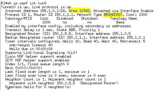
Type 2 LSA Network LSA is generated in Broadcast network.


With the broadcast network type, the DR does not update the next-hop. 


In Broadcast network, type 2 Network LSA is available since there is a DR. From outside, the whole subnet 155.1.0.0/24 is learnt.


Ospf Point-to-point network will work with point-to-multipoint if we change the hello, dead timers.

There is no DR selection and so there is no type 2 LSA, but the router is advertising connected subnet as LSA Type 1. 


155.1.0.5 is the DMVPN hub and it changed the next hop as itself in the OSPF routes.

From outside of the area 123, 155.1.0.0/24 is learnt as the same way in Broadcast network.


The Non-Broadcast network type means that there will no be a DR/BDR election, and that hellos are exchanged as unicast. To unicast OSPF hellos, the neighbor statement must be configured under the OSPF process of the DR.

OSPF network type point-to-multipoint non-broadcast is essentially the same as network type point-to-multipoint, with one exception: Point-to-multipoint network type uses multicast hellos, whereas point-to-multipoint non-broadcast uses unicast hellos. Additionally, in non-broadcast mode, you can configure per-neighbor OSPF cost using the command neighbor <IP_ADDRESS> cost <value>. In "show ip ospf int", it appears as point-tomultipoint, which can be both broadcast and non-broadcast; there is no clear differentiation in the outputs between the two. The difference between the two types can be seen in the debug ip packet output.


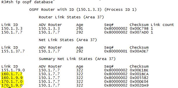
Similar to point-to-multipoint, an interface running network type Loopback is advertised as a stub endpoint instead of a transit subnet. The result of this network type that we see in our configuration is that when the Loopback160 interfaces of these devices are advertised into OSPF, they appear in
the routing table as /32 host routes instead of the actual subnet mask of /24. Because network type for Loopback170 interfaces is point-to-point, these are correctly advertised with their subnet mask.


Verify how these Loopbacks appear in the OPSF database.


From outside of that area, the routes are learnt as below. 


Cisco Labbing notes

Static Routes
-specify only the next-hop value; route is valid as long as a route exists for the nexthop value.
-Specify only the local outgoing interface; route is valid as long as the interface is in the UP/UP state.
-Specify both next-hop value and local outgoing interface.
When the third option is selected, the local outgoing interface behaves like a condition for the next-hop value and should be read like: this static route is valid only if the configured next-hop value is reachable over the configured interface, which means as long as the interface is in the UP/UP state and has nothing to do with IP/ARP/NHRP functionality with the next-hop.

When a router receives identical routes (prefix and prefix-length) through multiple routing protocols (static or dynamic), the decision regarding which one gets installed in the routing table is based on the lowest administrative distance; lower AD values have higher preference.

Recursive Routing Error
A recursive routing error is when a lookup for prefix X points at prefix Y for the next-hop, and a lookup for prefix Y points at prefix X for the next-hop. For tunnel interfaces, this occurs when the tunnel destination is dynamically learned through the tunnel interface itself.
In general, there are several solutions to the problem, depending on the IPv4 addressing scheme, routing protocol being used, and network design:

  • Do not advertise in the routing protocol the same networks over both the physical/Ethernet path and the tunneling/GRE path.
  • Do not advertise in the routing protocol used over the tunneling/GRE path the tunnel endpoints.
  • Use route filtering techniques to filter tunnel endpoints IPv4 addresses from being learned over the GRE tunnel.
  • Do not use same routing protocol over both the physical and tunneling paths; this is recommended but it requires correct routing protocol configuration.


GRE Tunnel
By default, the state of a point-to-point GRE interface is determined by routing availability for the tunnel destination. Therefore, as long as the router has a route for the tunnel destination, the tunnel interface state will be UP. This, however, does not account for possible transit problems or devices filtering GRE which is IP protocol number 47. To fix the problem, GRE keepalives can be enabled on point-to-point GRE tunnels. GRE keepalives are implemented in such a way that it can be enabled on one side of the tunnel only, which means only that side can track end-to-end GRE connectivity between the tunnel endpoints and update the GRE interface status accordingly.
The state of multipoint GRE tunnel interfaces, such as those used in DMVPN scenarios, cannot be monitored through GRE keepalives, because there is no single destination for the tunnel. The mGRE tunnel interface is always in the UP state.

ODR
On-Demand Routing (ODR) uses Cisco Discovery Protocol (CDP) to advertise connected IPv4 routes of a stub router to the hub. The hub router then advertises a default IPv4 route back to the spokes via CDP. For ODR to be functional, there should be no dynamic routing protocol configured on spokes.

Route Filtering (RIP)
When extended access-lists are used as distribute-list for IGP filtering, the functionality is different than when used for route redistribution or in BGP. With BGP and redistribution, the source field in the ACL represents the network address, and the destination field represents the subnet mask. In IGP distribute-list application, the source field in the ACL matches the update source of the route, and the destination field represents the network address.

The distance command can be used to change the administrative distance globally for the routing process, globally for the routing process per route type (external vs.internal), on a per-prefix basis, or on a per-neighbor per-prefix basis. The two fields after the distance value are the source of the route (RIP speaker) and a wildcard mask to match the source. The value needed for the source is seen in the above output in the from 155.1.37.3 field.
!
access-list 2 permit 150.1.3.3
!
router rip
distance 255 155.1.37.3 0.0.0.0 2
!
----------------------

EIGRP Auto-Summary
With EIGRP auto-summary enabled, VLSM is supported, but only for subnets that are within the same major network boundary(e.g. 192.168.10.0/24 and 192.168.20.0/24 but not 192.168.10.0/25 and 192.168.10.128/25). As network advertisements pass between major network boundaries, they are automatically summarized to their classful mask. The result of this behavior is that EIGRP cannot support discontiguous major networks. Although all of the routers are advertising the classful summary of their Loopback subnet 150.1.0.0/16 to all of their neighbors, each router also installs a local EIGRP summary route to Null0. The end result is that they cannot learn about each other's summaries to 150.1.0.0/16, and reachability is not obtained between these networks.

Summarization
When a summary is configured in EIGRP, all subnets that make up the summary are suppressed from being advertised out the link. From a design perspective, this feature can be used to both reduce the size of the routing table and limit the scope of EIGRP query messages.

The EIGRP leak-map feature of the summary-address allows the advertisement of specific subnets encompassed by the interface-level summary, similar to the unsuppress-map feature of BGP aggregation. Routes matched in the leak-map routemap will be advertised in addition to the summary.

When summaries are created in EIGRP, OSPF, and BGP, the router automatically installs a route to Null0 to match the summary. This is used to prevent the router from forwarding traffic for destinations inside the summary that it does not have a longer match for. However, in certain designs this can be an undesirable behavior. To resolve this, EIGRP sets its interface-level summaries to have an administrative distance of 5 by default. This means that any other route with a distance of 1–4 will take precedence over the summary.

Redistribution
Unlike BGP, filtering with route-maps in IGP is usually limited to redistribution filtering only. However, EIGRP supports route-map filtering as a distribute-list with matches on metric and tag values.
EIGRP uses the router-id field in external routes as a loop prevention mechanism.

EIGRP Composite Metric 
Use "metric weight 0 K1 K2 K3 K4 K5" command. K1 bandwidth and K3 Delay are set to 1; the rest 0 by default.

EIGRP Timers
Unlike OSPF, EIGRP hello and hold-time intervals do not need to match to form adjacencies. Just like OSPF, the locally configured Hello interval defines the local rate interval for sending EIGRP hello packets, but the value is not transmitted in EIGRP Hello packets. Unlike OSPF, the locally configured Hold-Time interval defines for how long the remote router will wait for a EIGRP packet before resetting the adjacency, so the value is transmitted in EIGRP Hello packets.

The passive-interface command in EIGRP, like in RIPv2, stops the sending of updates out an interface. Unlike RIPv2, however, passive-interface in EIGRP will prevent forming of an adjacency on the interface because it stops sending EIGRP Hello packets as well, and hence the learning of any updates on the link.